
Power Solution

You all must have heard about inverters and might have a sound knowledge of what they are. But are you aware of a voltage source inverter? Let us learn more about it. A voltage source inverter, often known as a VSI, is a converter that changes a voltage’s waveform from unidirectional to bidirectional, or from DC to AC. The optimum voltage source inverter maintains a consistent voltage throughout the operation.
Source: Luminous
A VSI typically consists of one sizable DC link capacitor, a transistor for switching, a DC voltage source, and a DC voltage source. A transistor utilized might be an IGBT, BJT, MOSFET, or GTO. A DC voltage source might also be a battery, dynamo, or solar cell. The two topologies of VSI are three-phase and single-phase inverters, with each phase, further subdivided into half-bridge and full-bridge inverters.
There are two primary parts that make up a balanced load: a source and a load. A balanced source implies that phase and magnitude are equal and that they are phase-shifted by 120 degrees.
The balanced load implies that all load impedances in all three phases are equal in magnitude and phase, in accordance with the KCL principle. Thyristors T1, T3, and T5 give current to the load or serve as forwarding paths, whilst thyristors T6, T4, and T2 serve as return paths and transport the current back to the source.
There are two conduction moods in which a voltage source inverter can operate:
Let us take a look at the case of a three-phase inverter operating in a 180-degree conduction mode. Because both switches S1 and S2 conduct at 180 degrees, the three-phase inverter is depicted in 180-degree conduction mode. In contrast, all four switches (S1, S2, S3, S4) in a full-bridge voltage source inverter conduct at 180 degrees. The switches T1 and T4 are coupled to a phase, which T1 and T4 conduct at 180 degrees each, according to the circuit diagram below, where the total length is indicated as 1800 + 1800 = 3600. A short circuit could result if both switches operate at the same time.
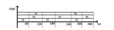
The graph, which has wt as the X-axis and amplitude as the Y-axis, shows that
The table below illustrates the difference
| Voltage Source Inverter | Current Source Inverter |
| The inverter is often provided with a rigid voltage source. | The inverter is already equipped with a powerful current source. |
| A DC source’s low internal impedance necessitates the use of feedback diodes | A DC source’s high internal impedance not having feedback diodes |
| The capacitor causes a minor variation in output voltage | A change in load causes a change in output voltage. |
| Complicated structuring | Simple structuring |
| Decreased output impedance | Increased output impedance |
These are some uses for voltage source inverter.
So, an inverter is a piece of equipment that changes dc into ac. Current source inverter and voltage source inverters are two categories of self-commutated inverters. A device that changes a voltage’s shape from DC to AC is known as a voltage source inverter.
Either one phase or three phases might be used to represent it. The function of the 3-phase VSI is explained in the following article. Where each phase has a conduction mood of 180 degrees and 120 degrees. The key benefit is that the output voltage is unaffected by the applied load.
We hope this blog provided you with in depth knowledge about Voltage Source Inverter. If you are keen to know more about current source inverter or single phase voltage source inverter, check our website and explore a whole new world inverters and batteries!

